The distance between the posts when stretching the sip. Design parameters of overhead power lines
How to choose the maximum and minimum span length,
The maximum and minimum span lengths are selected according to a typical design; the tables provide all the information when using a specific section and brand of SIP
In the end it counts...
sag
You make an additional sheet in the working documentation where all the necessary data are given depending on the ambient temperature. environment and span length
after all, where should the supports be (where are the anchors, where are the intermediate ones, when should the corner supports be anchors?),
Anchor end - installed at the beginning and end of the line capable of withstanding tension on one side (usually two-column, or single-column with a brace ... see typical)
Intermediate - installed on a straight section (without bends, preferably with the same spans before and after) withstands the tension of the wires from 2 sides so that the resultant force \u003d 0
Angular intermediate - depending on the type you use, it sets the angle of rotation of the route, for example, up to 30 degrees. It is carried out by either a reinforced stand or a guy line, by digging into the pit, see typical.
Angle anchor - as a rule, it allows you to turn the route up to 90 degrees. see typical
In places where wires of different cross-sections are built up, an Anchor support is used.
what is a lantern wire anyway
a wire that is pulled together with a 3-phase and neutral conductor. The 5th wire is used to connect and control lights (5th wire + 0-wire = 220V)
Example of SIP4 4x50 + 25, respectively, the cross section of the 5th wire is 25 mm2
But what if I don’t need branches (throw a maximum of wiring on the lamp)?
the boss simply inserted the leaves from the standard project as is. Upon agreement, he stipulated that there were no branches, and only fittings for the main were laid in the specification
as for me, I deleted the branches - I did it as it really is! There were a lot fewer questions when agreeing!
YES, do not forget that on the VLI supports of 0.4 kV, you need to re-ground (on the first, on the last, and every 200 m), you ground the neutral wire, the VLI fittings. look more precisely
PUE "Grounding. Overvoltage protection" 2.4.46 ... The resistance of the charger should be no more than 30 Ohm
For VLZ supports of 10 kV, it is necessary to carry out grounding on each "support" you ground the VLZ fittings.
By the way, the entrance to the building ... FOR VLI 0.4 kV SIP4 fittings ENSTO
These guides contain links to typical keep in mind that the supports must be taken from the same series of the standard.
FOR SIP4 (all cores are insulated, all cores are load-bearing), 1o 2x chain, wood / reinforced concrete
For SIP 1A, SIP 2A (with insulated neutral conductor), 1o 2x chain, wood / reinforced concrete
For SIP 1, SIP 2 (with uninsulated neutral conductor), 1o 2x chain, wood / reinforced concrete
For VLZ 6-20 kV Zh.B. supports. Volume 1. Single-chain and double-chain reinforced concrete supports.
For VLZ 6-20 kV Wooden poles. Volume 2. Designs of single-chain and double-chain wooden supports
Who did not manage to find the mounting arrows of the sag, then here ...
Here are the mounting booms for VLI 0.4 kV (SIP4 wire) and VLZ 10kV (SIP3 wire)
Good afternoon! Condition of the problem: a pole with an electric cabinet (there is a counter, etc.) and a wooden (beam) house at a distance of 40 meters, i.e. the connection is NOT from the main line. It is necessary to bring electricity to the house (3 phases, 4 wires!!!). Which wire should be used for the overhead line? We are looking at SIP 4x16 (relatively light and inexpensive, and the Internet advises for air lines, but advice is usually from the main to the meter in the house), but it is aluminum, and the wiring in the house is copper, and it is not clear whether it can be brought directly into the house (in a corrugation, in a metal pipe or something else), maybe copper is better right away?
Fastener manufacturers claim that the SIP itself (without supporting cables) can be hung in spans up to 40m, and the “main” ones in the village are all at about the same interval, but there are recommendations - no more than 25 meters. + still has a braided cable.
So the questions are:
1) Is there a reasonable alternative to SIP? Perhaps a copper alternative directly to the "home" shield from the street meter? Which one?
2) Is it necessary to install additional support for SIP or alternatives (see above)? Or is SIP + braided cable enough for a 40 meter span? And if not light SIP, but copper, then how?
3) If you need a support, then (because the weight is small) will a beam like 150x150 fit?
4) Can SIP be introduced into a metal pipe or corrugation into the house to the “home” machine in the corridor? Or not to be smart and switch to copper on the street near the house? I repeat!!! the connection is NOT from the highway, but from the meter to the house (it so happened that they were separated)
Rules for the installation of electrical installations
7th edition
Section 2 Electricity transmission
Chapter 2.4 Overhead power lines with voltage up to 1 kV
Introduction date 2003-10-01
Foreword
Developed taking into account the requirements of state standards, building codes and regulations, recommendations of scientific and technical councils for reviewing draft chapters. The draft chapters were reviewed by the working groups of the Coordinating Council for the revision of the EMP
Prepared by JSC "ROSEP", co-executor - JSC "Firm ORGRES"
AGREED in the prescribed manner with the Gosstroy of Russia, Gosgortekhnadzor of Russia, RAO "UES of Russia" (JSC "VNIIE") and submitted for approval by the Gosenergonadzor of the Ministry of Energy of Russia
From October 1, 2003, Chapter 2.4 of the "Electrical Installation Rules" of the sixth edition becomes invalid
The requirements of the Electrical Installation Rules are mandatory for all organizations, regardless of ownership and organizational and legal forms, as well as for individuals engaged in entrepreneurial activities without forming a legal entity.
Application area. Definitions
2.4.1. This chapter of the Rules applies to overhead power lines alternating current voltage up to 1 kV, performed using insulated or bare wires.
Additional requirements for overhead lines up to 1 kV are given in chapters 2.5, 6.3 and 7.7.
Cable inserts into the line and cable branches from the line must be made in accordance with the requirements of Chapter 2.3.
2.4.2. Overhead line (VL) of power transmission with voltage up to 1 kV - a device for the transmission and distribution of electricity through insulated or non-insulated wires located in the open air and attached by linear fittings to supports, insulators or brackets, to building walls and to engineering structures.
An overhead power line with a voltage of up to 1 kV using self-supporting insulated wires (SIP) is designated VLI.
Self-supporting insulated wire - insulated conductors twisted into a bundle, and the carrier conductor can be either insulated or uninsulated. The mechanical load can be taken either by the carrier conductor or by all conductors of the bundle.
2.4.3. Highway VL - a section of the line from the supply transformer substation to the end support.
Linear branches or branches to the input can be connected to the overhead line.
Linear branch from the overhead line - a section of the line connected to the main overhead line, having more than two spans.
A branch from the overhead line to the input is the section from the support of the main line or linear branch to the clamp (input insulator).
A branch from the VLI is allowed to be performed in the span.
2.4.4. The state of the overhead line in the calculations of the mechanical part:
normal mode - mode with unbroken wires;
emergency mode - mode with broken wires;
installation mode - mode in the conditions of installation of supports and wires.
Mechanical calculation of overhead lines up to 1 kV in emergency mode is not performed.
General requirements
2.4.5. The mechanical calculation of the elements of the overhead line should be carried out according to the methods described in Chapter 2.5.
2.4.6. Overhead power lines should be placed so that the supports do not block the entrances to buildings and entrances to courtyards and do not impede the movement of vehicles and pedestrians. In places where there is a danger of collision with vehicles (at the entrances to yards, near exits from roads, at the intersection of roads), the supports must be protected from collision (for example, by bollards).
2.4.7. On the overhead line supports at a height of at least 2 m from the ground after 250 m on the overhead line, the following should be installed (applied): the serial number of the support; posters showing the distances from the overhead line pole to the cable communication line (on poles installed at a distance of less than 4 m to the communication cables), the width of the security zone and the phone number of the overhead line owner.
2.4.8. When passing VLI through forests and green spaces, clearing is not required. At the same time, the distance from the wires to trees and bushes with the largest SIP sag and their largest deviation should be at least 0.3 m.
When passing overhead lines with uninsulated wires through forests and green spaces, cutting down the clearing is not necessary. At the same time, the distance from the wires with the largest sag or the largest deviation to trees and bushes should be at least 1 m.
The distance from insulated wires to green spaces should be at least 0.5 m.
2.4.9. The structures of the overhead line supports must be protected from corrosion, taking into account the requirements of 2.5.25, 2.5.26 and building codes and regulations.
2.4.10. Protection of overhead lines from electrical overloads should be carried out in accordance with the requirements of Chapter 3.1.
Climatic conditions
2.4.11. Climatic conditions for the calculation of overhead lines up to 1 kV in normal mode should be taken as for overhead lines up to 20 kV in accordance with 2.5.38-2.5.74. In this case, for overhead lines up to 1 kV, the following should be taken:
when calculating according to 2.5.52: \u003d 1.1 - for SIP, free or covered with ice;
when calculating according to 2.5.54 and 2.5.55:
0.8 - for single-circuit overhead lines;
0.9 - for single-circuit overhead lines with suspension on PV supports;
1.0 and 1,2 - for double-circuit and multi-circuit overhead lines, as well as when suspended on overhead line supports of a self-supporting non-metallic optical cable (OKSN);
1.0 and 1.0 - in all cases.
2.4.12. The calculation of the span length of the branch from the overhead line to the input according to 2.4.20 must be carried out in icy conditions for two cases:
1) wind direction at an angle of 90 ° to the axis of the overhead line, the wires of the overhead line are covered with icebuh, wall thickness of ice on branch wiresb0 =0,5 buh;
2) wind direction along the overhead line (angle 0°), ice wall thickness on branch wiresb0 = buh.
In this case, in both cases, one should take into account the reduction in the tension of the branch wires when the top of the support is deflected.
Wires. Linear reinforcement
2.4.13. On overhead lines, as a rule, self-supporting insulated wires (SIPs) should be used.
SIP must be classified as protected, have insulation from a slow-burning, light-stabilized synthetic material that is resistant to ultraviolet radiation and exposure to ozone.
2.4.14. According to the conditions of mechanical strength on the mains of the overhead line, on the linear branch from the overhead line and on the branches to the inputs, wires with the minimum sections indicated in tables 2.4.1 and 2.4.2 should be used.
Table 2.4.1
Minimum allowable sections of insulated wires
| buh, mm | Cross-section of the bearing core, , on the VLI highway, on a linear branch from the VLI | The cross section of the core on the branches from the VLI and from the VL to the inputs, |
| 35 (25) * | ||
| 15 or more | 50 (25) * |
________________
* In parentheses is the cross section of the core of self-supporting insulated wires twisted into a bundle, without a carrier wire.
Table 2.4.2
Minimum allowable sections of bare and insulated wires
| Normative ice wall thicknessbuh, mm | Wire material | Wire cross-section on the main and linear branch, mm |
| Aluminum (A), non-heat-treated aluminum alloy (AN) | ||
| Steel-aluminum (AS), heat treated aluminum alloy (AH) | ||
| Copper (M) | ||
| 15 or more | A, AN AS, AZh M | |
2.4.15. When constructing overhead lines in places where operating experience has established the destruction of wires from corrosion (the coasts of the seas, salt lakes, industrial areas and areas of saline sands), as well as in places where, based on survey data, it is possible, self-supporting insulated wires with an insulated core should be used. .
2.4.16. The overhead line, as a rule, should be carried out with wires of a constant cross section.
The cross sections of the phase wires of the HP main are recommended to be taken at least 50 .
2.4.17. The mechanical calculation of wires shall be carried out according to the allowable stress method for the conditions specified in 2.5.38-2.5.74. In this case, the voltages in the wires should not exceed the allowable voltages given in Table 2.4.3, and the distances from the wires to the ground surface, intersected structures and grounded support elements must meet the requirements of this chapter.
Table 2.4.3
Permissible mechanical stress in the wires of overhead lines up to 1 kV
| The wire | Permissible voltage, % tensile strength |
|
| at highest load and lowest temperature | at an average annual temperature |
|
| SIP section 25-120 | ||
| aluminum section, : | ||
| 25-95 | ||
| From heat-treated and non-heat-treated aluminum alloy with a cross section, : | ||
| 25-95 | ||
| steel-aluminum section, : | ||
| 35-95 | ||
When calculating, the wire parameters given in Table 2.5.8 are used.
2.4.18. All types of mechanical loads and impacts on SIP with a carrier core should be taken by this core, and on SIP without a carrier wire, all cores of a twisted bundle should be perceived.
2.4.19. The length of the span of the branch from the overhead line to the input should be determined by calculation depending on the strength of the support on which the branch is performed, the height of the suspension of the branch wires on the support and at the input, the number and cross section of the wires of the branch wires.
At distances from the overhead line to the building exceeding the calculated span of the branch, the required number of additional supports is installed.
2.4.20. The choice of the cross section of current-carrying conductors for long-term permissible current should be carried out taking into account the requirements of Chapter 1.3.
The cross section of current-carrying conductors should be checked according to the condition of heating at short circuits(KZ) and thermal stability.
2.4.21. Fastening, connection of the SIP and connection to the SIP should be done as follows:
1) fastening the wire of the VLI highway on intermediate and angular intermediate supports - using supporting clamps;
2) fastening the wire of the VLI main on anchor-type supports, as well as the end fastening of the branch wires on the VLI support and at the input - using tension clamps;
3) connection of the VLI wire in the span - using special connecting clamps; in the loops of anchor-type supports, it is allowed to connect an uninsulated carrier wire using a ram clamp. Connecting clamps designed to connect the carrier wire in the span must have a mechanical strength of at least 90% of the breaking force of the wire;
4) connection of the phase wires of the VLI line - using connecting clamps having an insulating coating or a protective insulating sheath;
5) connection of wires in the span of a branch to the input is not allowed;
6) connection of grounding conductors - using flat clamps;
7) branch clamps should be used in the following cases:
branches from phase conductors, with the exception of SIP with all carrier conductors of the bundle;
branches from the carrier core.
2.4.22. Fastening of supporting and tension clamps to VLI supports, walls of buildings and structures should be carried out using hooks and brackets.
2.4.23. The calculated forces in the support and tension clamps, attachment points and brackets in normal mode should not exceed 40% of their mechanical breaking load.
2.4.24. Wire connections in spans of overhead lines should be made using connecting clamps that provide mechanical strength of at least 90% of the breaking force of the wire.
In one span of overhead lines, no more than one connection is allowed for each wire.
In the spans of the intersection of overhead lines with engineering structures, the connection of overhead lines is not allowed.
The connection of wires in the loops of the anchor supports should be made using clamps or welding.
Wires of different brands or sections should be connected only in the anchor support loops.
2.4.25. It is recommended to fasten uninsulated wires to insulators and insulating traverses on overhead line supports, with the exception of supports for crossings, as a single one.
Fastening of bare wires to pin insulators on intermediate supports should be carried out, as a rule, on the neck of the insulator on its inner side with respect to the support post.
2.4.26. Hooks and pins should be calculated in the normal mode of operation of the overhead line according to the method of breaking loads.
In this case, the forces shall not exceed the values given in 2.5.101.
Arrangement of wires on poles
2.4.27. On supports, any arrangement of insulated and uninsulated wires of overhead lines is allowed, regardless of the area of \u200b\u200bclimatic conditions. The neutral wire of overhead lines with bare wires, as a rule, should be located below the phase wires. Insulated outdoor lighting wires laid on VLI supports can be placed above or below the SIP, and also be twisted into a SIP bundle. Uninsulated and insulated outdoor lighting wires laid on overhead line supports should, as a rule, be located above PEN (PE) conductor VL.
2.4.28. Devices mounted on supports for connecting electrical receivers must be placed at a height of at least 1.6 m from the ground.
Protective and sectioning devices installed on supports should be placed below the wires of the overhead line.
2.4.29. The distances between uninsulated wires on the support and in the span, according to the conditions of their convergence in the span with the largest sag up to 1.2 m, must be at least:
with a vertical arrangement of wires and an arrangement of wires with a horizontal displacement of not more than 20 cm: 40 cm in I, II and III regions on ice, 60 cm in IV and special regions on ice;
at other locations of wires in all areas on ice at wind speed on ice: up to 18 m / s - 40 cm, more than 18 m / s - 60 cm.
With the largest sag of more than 1.2 m, the indicated distances must be increased in proportion to the ratio of the largest sag to the sag of 1.2 m.
2.4.30. The vertical distance between insulated and non-insulated wires of overhead lines of different phases on a support at a branch from an overhead line and at the intersection of different overhead lines on a common support must be at least 10 cm.
The distance from the wires of the overhead line to any support elements must be at least 5 cm.
2.4.31. When jointly suspended on common supports of VLI and VL up to 1 kV, the vertical distance between them on the support and in the span at an ambient temperature of plus 15 ° C without wind should be at least 0.4 m.
2.4.32. When two or more VLIs are jointly suspended on common supports, the distance between the SIP bundles must be at least 0.3 m.
2.4.33. When jointly suspended on common supports of wires of overhead lines up to 1 kV and wires of overhead lines up to 20 kV, the vertical distance between the nearest wires of overhead lines of different voltages on a common support, as well as in the middle of the span at an ambient temperature of plus 15 ° C without wind, should be at least:
1.0 m - when hanging SIP with an insulated carrier and with all carrier wires;
1.75 m - when hanging SIP with uninsulated carrier wire;
2.0 m - when hanging uninsulated and insulated wires of overhead lines up to 1 kV.
2.4.34. When hanging on common supports wires of overhead lines up to 1 kV and protected wires of overhead lines 6-20 kV (see 2.5.1), the vertical distance between the nearest wires of overhead lines up to 1 kV and overhead lines 6-20 kV on the support and in the span at a temperature of plus 15 ° С without wind should be at least 0.3 m for SIP and 1.5 m for uninsulated and insulated wires of overhead lines up to 1 kV.
Insulation
2.4.35. Self-supporting insulated wire is attached to the supports without the use of insulators.
2.4.36. On overhead lines with uninsulated and insulated wires, regardless of the material of the supports, the degree of atmospheric pollution and the intensity of lightning activity, insulators or traverses made of insulating materials should be used.
Selection and calculation of insulators and fittings are carried out in accordance with 2.5.100.
2.4.37. On the supports of branches from overhead lines with uninsulated and insulated wires, as a rule, multi-neck or additional insulators should be used.
Grounding. Surge protection
2.4.38. Grounding devices designed for re-grounding, protection against lightning surges, grounding of electrical equipment installed on overhead line supports must be made on the overhead line supports. The resistance of the grounding device must be no more than 30 ohms.
2.4.39. Metal supports, metal structures and reinforcement of reinforced concrete elements of supports must be attached to REN- conductor.
2.4.40. On reinforced concrete supports REN- the conductor should be connected to the reinforcement of reinforced concrete racks and support struts.
2.4.41. Hooks and pins of wooden poles of overhead lines, as well as metal and reinforced concrete poles when suspended on them with an insulated carrier conductor or with all carrier conductors of the bundle, are not subject to grounding, with the exception of hooks and pins on the poles, where repeated grounding and grounding are performed to protect against atmospheric overvoltages.
2.4.42. Hooks, pins and fittings of overhead lines with a voltage of up to 1 kV, limiting the crossing span, as well as supports on which joint suspension is carried out, must be grounded.
2.4.43. On wooden poles of overhead lines, when moving to a cable line, the grounding conductor must be connected to REN- the conductor of the overhead line and to the metal sheath of the cable.
2.4.44. Protective devices installed on overhead lines for protection against lightning surges must be connected to the grounding conductor with a separate descent.
2.4.45. The connection of the grounding conductors to each other, their connection to the upper grounding outlets of the racks of reinforced concrete supports, to hooks and brackets, as well as to grounded metal structures and to grounded electrical equipment installed on overhead line supports, must be carried out by welding or bolted connections.
The connection of grounding conductors (descents) to the grounding conductor in the ground must also be carried out by welding or have bolted connections.
2.4.46. In a populated area with one- and two-story buildings, overhead lines must have grounding devices designed to protect against atmospheric surges. The resistance of these grounding devices should be no more than 30 ohms, and the distances between them should be no more than 200 m for areas with up to 40 thunderstorm hours per year, 100 m for areas with more than 40 thunderstorm hours per year.
In addition, grounding devices must be made:
1) on supports with branches to the entrances to buildings in which a large number of people can be concentrated (schools, nurseries, hospitals) or which are of great material value (livestock and poultry premises, warehouses);
2) on the end supports of lines having branches to the inputs, while the greatest distance from the adjacent grounding of these same lines should be no more than 100 m for areas with a number of thunderstorm hours per year up to 40 and 50 m - for areas with a number of thunderstorm hours per year over 40.
2.4.47. At the beginning and end of each VLI line, it is recommended to install clamps on the wires for connecting voltage control devices and portable grounding.
Grounding lightning surge protection devices are recommended to be combined with re-grounding REN-conductor.
2.4.48. Requirements for grounding devices for re-grounding and protective conductors are given in 1.7.102, 1.7.103, 1.7.126. As grounding conductors on overhead line supports, it is allowed to use round steel with an anti-corrosion coating with a diameter of at least 6 mm.
2.4.49. Guys of overhead lines must be connected to the ground conductor.
supports
2.4.50. Supports made of various materials can be used on overhead lines.
For overhead lines, the following types of supports should be used:
1) intermediate, installed on straight sections of the overhead line route. These supports in normal operating modes should not perceive the forces directed along the overhead line;
2) anchor, installed to limit the anchor span, as well as in places where the number, grades and cross sections of overhead lines change. These supports should perceive, in normal operating modes, the forces from the difference in the tension of the wires directed along the overhead line;
3) angular, installed in places where the direction of the overhead line changes direction. These supports, under normal operating conditions, must perceive the resulting load from the tension of the wires of adjacent spans. Corner supports can be intermediate and anchor type;
4) terminal, installed at the beginning and end of the overhead line, as well as in places limiting cable inserts. They are anchor-type supports and must perceive, in normal operating modes of overhead lines, the one-sided tension of all wires.
Supports on which branches from overhead lines are carried out are called branch; supports on which the intersection of overhead lines of different directions or the intersection of overhead lines with engineering structures is carried out - cross. These supports can be of all the above types.
2.4.51. Support structures should provide the ability to install:
lamps street lighting all types;
end cable couplings;
protective devices;
sectioning and switching devices;
cabinets and shields for connecting electrical receivers.
2.4.52. Supports, regardless of their type, can be free-standing, with braces or braces.
Support guys can be attached to anchors installed in the ground, or to stone, brick, reinforced concrete and metal elements of buildings and structures. The cross section of the guys is determined by calculation. They can be stranded or round steel. The cross section of single-wire steel braces must be at least 25 .
2.4.53. The overhead line supports must be calculated according to the first and second limit state in the normal operation of the overhead line for climatic conditions according to 2.4.11 and 2.4.12.
Intermediate supports must be designed for the following combinations of loads:
simultaneous action of transverse wind load on wires, free or covered with ice, and on the structure of the support, as well as the load from the tension of branch wires to inputs, free from ice or partially covered with ice (according to 2.4.12);
on the load from the tension of the wires of the branches to the inputs covered with ice, while it is allowed to take into account the deviation of the support under the action of the load;
to conditional design load, equal to 1.5 kN, applied to the top of the support and directed along the axis of the overhead line.
Corner supports (intermediate and anchor) must be designed for the resulting load from the tension of the wires and the wind load on the wires and the structure of the support.
Anchor supports must be designed for the difference in tension of the wires of adjacent spans and the transverse load from wind pressure with and without ice on the wires and the support structure. For the smallest value of the tension difference, 50% of the largest value of the unilateral tension of all wires should be taken.
End supports must be designed for one-sided tension of all wires.
Branch supports are calculated for the resulting load from the tension of all wires.
2.4.54. When installing supports on flooded sections of the route, where soil erosion or ice drift is possible, the supports must be strengthened (earth filling, paving, banquettes, installation of ice cutters).
Dimensions, intersections and convergence
2.4.55. The vertical distance from the VLI wires to the ground surface in populated and uninhabited areas to the ground and the carriageway of the streets must be at least 5 m. It can be reduced in hard-to-reach areas up to 2.5 m and inaccessible (mountain slopes, rocks, cliffs) - up to 1 m.
When crossing the impassable part of the streets with branches from the VLI to the inputs to the buildings, the distance from the SIP to the sidewalks of the footpaths can be reduced to 3.5 m.
The distance from the SIP and insulated wires to the ground on the branches to the input must be at least 2.5 m.
The distance from bare wires to the ground surface on the branches to the inputs must be at least 2.75 m.
2.4.56. The distance from the wires of the overhead line in populated and uninhabited areas with the largest sag of the wires to the ground and the carriageway of the streets must be at least 6 m. The distance from the wires to the ground can be reduced in hard-to-reach areas to 3.5 m and in inaccessible areas (mountain slopes , rocks, cliffs) - up to 1 m.
2.4.57. The horizontal distance from the SIP at their greatest deviation to the elements of buildings and structures should be at least:
1.0 m
0.2 m - to the blank walls of buildings, structures.
It is allowed to pass VLI and VL with insulated wires over the roofs of buildings and structures (except for those specified in Chapters 7.3 and 7.4), while the vertical distance from them to the wires must be at least 2.5 m.
2.4.58. The horizontal distance from the wires of the overhead line with their greatest deviation to buildings and structures should be at least:
1.5 m - to balconies, terraces and windows;
1.0 m - to blank walls.
The passage of overhead lines with bare wires over buildings and structures is not allowed.
2.4.59. The smallest distance from SIP and overhead lines to the surface of the earth or water, as well as to various structures when passing overhead lines over them, is determined at the highest air temperature without taking into account the heating of overhead lines by electric current.
2.4.60. When laying along the walls of buildings and structures, the minimum distance from the SIP should be:
with horizontal laying
above the window, front door - 0.3 m;
under the balcony, window, cornice - 0.5 m;
to the ground - 2.5 m;
with vertical laying
to the window - 0.5 m;
to the balcony, front door - 1.0 m.
The clear distance between the SIP and the wall of the building or structure must be at least 0.06 m.
2.4.61. Horizontal distances from the underground parts of supports or earthing supports to underground cables, pipelines and ground columns for various purposes must be at least those given in Table 2.4.4.
Table 2.4.4
The smallest allowable horizontal distance from the underground parts of towers or grounding devices of towers to underground cables, pipelines and ground columns
| Proximity object | Distance, m |
| Water, steam and heat pipelines, gas distribution pipelines, sewer pipes | |
| Fire hydrants, wells, sewer manholes, standpipes | |
| Cables (except for communication cables, signaling and wire broadcasting, see also 2.4.77) | |
| The same, but when laying them in an insulating pipe |
2.4.62. When crossing overhead lines with various structures, as well as with streets and squares of settlements, the intersection angle is not standardized.
2.4.63. Crossing overhead lines with navigable rivers and canals is not recommended. If it is necessary to perform such an intersection, overhead lines must be constructed in accordance with the requirements of 2.5.268-2.5.272. When crossing non-navigable rivers and canals, the shortest distances from the overhead line wires to the highest water level should be at least 2 m, and to the ice level - at least 6 m.
2.4.64. The intersection and convergence of overhead lines with voltage up to 1 kV with overhead lines with voltage above 1 kV, as well as the joint suspension of their wires on common supports, must be carried out in compliance with the requirements given in 2.5.220-2.5.230.
2.4.65. It is recommended to cross overhead lines (VLI) up to 1 kV on cross supports; their intersection in the span is also allowed. The vertical distance between the wires of intersecting overhead lines (VLI) must be at least: 0.1 m on the support, 1 m in the span.
2.4.66. At the intersection of overhead lines up to 1 kV, intermediate supports and anchor-type supports can be used with each other.
When crossing overhead lines up to 1 kV between themselves in the span, the intersection should be chosen as close as possible to the support of the upper crossing overhead line, while the horizontal distance from the supports of the crossing overhead line to the wires of the crossed overhead line with their greatest deviation should be at least 2 m.
2.4.67. With parallel passage and approach of overhead lines up to 1 kV and overhead lines above 1 kV, the horizontal distance between them must be at least those specified in 2.5.230.
2.4.68. Joint suspension of wires of overhead lines up to 1 kV and uninsulated wires of overhead lines up to 20 kV on common supports is allowed subject to the following conditions:
2) wires of overhead lines up to 20 kV should be located above the wires of overhead lines up to 1 kV;
3) wires of overhead lines up to 20 kV, fixed on pin insulators, must have a double fastening.
2.4.69. When hanging on common supports wires of overhead lines up to 1 kV and protected wires of 6-20 kV overhead lines, the following requirements must be observed:
1) VL up to 1 kV must be carried out according to the design climatic conditions VL up to 20 kV;
2) wires of VLZ 6-20 kV should be located, as a rule, above the wires of overhead lines up to 1 kV;
3) fastening of wires of VLZ 6-20 kV on pin insulators must be reinforced.
2.4.70. When crossing an overhead line (VLI) with an overhead line with a voltage above 1 kV, the distance from the wires of the crossing overhead line to the crossed overhead line (VLI) must comply with the requirements given in 2.5.221 and 2.5.227.
The cross section of the wires of the crossed overhead line should be taken in accordance with 2.5.223.
Intersections, convergence, joint suspension of overhead lines with communication lines, wire broadcasting and RK
2.4.71. The angle of intersection of the overhead line with the LAN * and LPV should be as close as possible to 90 °. For cramped conditions, the intersection angle is not standardized.
_______________
* LAN should be understood as communication lines of the Ministry of Communications of the Russian Federation and other departments, as well as signaling lines of the Ministry of Railways.
LPV should be understood as wire broadcasting lines.
According to their purpose, overhead communication lines are divided into long-distance telephone lines (MTS), rural telephone lines (STS), city telephone lines (GTS), wire broadcasting lines (LPV).
In terms of importance, overhead communication lines and wire broadcasting are divided into classes:
MTS and STS lines: MTS main lines connecting Moscow with republican, regional and regional centers and the latter among themselves, and lines of the Ministry of Railways, passing along railways and across the territory of railway stations (class I); intrazonal MTS lines connecting republican, krai and regional centers with regional centers and the latter among themselves, and STS connecting lines (class II); STS subscriber lines (class III);
GTS lines are not divided into classes;
wire broadcasting lines: feeder lines with a rated voltage above 360 V (class I); feeder lines with rated voltage up to 360 V and subscriber lines with voltage 15 and 30 V (class II).
2.4.72. The vertical distance from the wires of the overhead line to the wires or overhead cables of the LAN and LPV in the crossing span with the largest sag of the wire of the overhead line should be:
from SIP and insulated wires - at least 1 m;
from bare wires - at least 1.25 m.
2.4.73. The vertical distance from the wires of the overhead line up to 1 kV to the wires or overhead cables of the LS or LPV when crossing on a common support should be:
between SIP and drugs or LPV - not less than 0.5 m;
between the uninsulated wire of the overhead line and the LPV - at least 1.5 m.
2.4.74. The intersection of the wires of the overhead line with wires or overhead cables of the LS and LPV in the span should be as close as possible to the overhead line support, but not less than 2 m from it.
2.4.75. The intersection of overhead lines with LS and LPV can be performed according to one of the following options:
1) wires of overhead lines and insulated wires of LS and LPV;
2) wires of overhead lines and underground or overhead cable LS and LPV;
3) wires of overhead lines and uninsulated wires of LS and LPV;
4) underground cable insert in overhead lines with insulated and uninsulated wires LS and LPV.
2.4.76. When crossing overhead lines with insulated wires LS and LPV, the following requirements must be observed:
2) the intersection of uninsulated overhead lines with LAN wires, as well as with LPV wires with voltages above 360 V, should be carried out only in the span. The intersection of uninsulated wires of overhead lines with wires of LPV with a voltage of up to 360 V can be performed both in the span and on a common support;
3) overhead line supports that limit the span of intersection with the LS of the main and intrazonal communication networks and the connecting lines of the STS, as well as the LPV with a voltage above 360 V, must be of the anchor type. At the intersection of all other LS and LPV, intermediate-type overhead lines are allowed, reinforced with an additional prefix or strut;
4) VL wires should be located above the LS and LPV wires. On the supports that limit the crossing span, uninsulated and insulated wires of overhead lines must be double fastened, the self-supporting insulated wire is fixed with anchor clamps. Wires LS and LPV on the supports that limit the span of the crossing must have a double fastening. In cities and urban-type settlements, newly built HP and LPV are allowed to be placed above the wires of overhead lines with a voltage of up to 1 kV.
2.4.77. When crossing overhead lines with an underground or overhead cable LS and LPV, the following requirements must be met:
1) the distance from the underground part of the metal or reinforced concrete support and the ground electrode of a wooden support to the underground cable LS and LPV in a populated area should, as a rule, be at least 3 m. at the same time, the cable must be laid in a steel pipe or covered with a channel or angle steel along the length on both sides of the support at least 3 m;
2) in an uninhabited area, the distance from the underground part or ground electrode of the overhead line support to the underground cable of the LS and LPV must be at least the values \u200b\u200bgiven in Table 2.4.5;
Table 2.4.5
The smallest distance from the underground part and the ground electrode of the overhead line support to the underground cable of the LS and LPV
in an uninhabited area
| Equivalent earth resistivity, Ohm m | The smallest distance, m, from the underground cable LS and LPV |
|||
| to the ground electrode or the underground part of the reinforced concrete and metal support | to the underground part of a wooden support that does not have a grounding device |
|||
| Up to 100 | ||||
| More than 100 to 500 | ||||
| More than 500 to 1000 | ||||
| Over 1000 | 5) the metal sheath of the overhead cable and the rope on which the cable is suspended must be grounded on supports that limit the crossing span; 6) the horizontal distance from the base of the cable support of the LS and LPV to the projection of the nearest wire of the overhead line on the horizontal plane must be at least the maximum height of the support of the crossing span. 2.4.78. When crossing VLI with uninsulated wires LS and LPV, the following requirements must be observed: 1) the intersection of the VLI with the LS and LPV can be performed in the span and on the support; 2) VLI supports, limiting the span of intersection with the LS of the main and intrazonal communication networks and with the connecting lines of the STS, must be of the anchor type. When crossing all other LS and LPV on VLI, it is allowed to use intermediate supports reinforced with an additional prefix or strut; 3) the carrier core of the self-supporting insulated wire or bundle with all carrier conductors at the intersection must have a tensile strength factor at the highest design loads of at least 2.5; 4) VLI wires should be located above the LS and LPV wires. On the supports that limit the crossing span, the supporting wires of the self-supporting insulated wire must be fixed with tension clamps. VLI wires are allowed to be placed under the LPV wires. At the same time, the LPV wires on the supports that limit the crossing span must have a double fastening; 5) the connection of the carrier core and the carrier conductors of the SIP bundle, as well as the LS and LPV wires in the crossing spans is not allowed. 2.4.79. When crossing insulated and uninsulated wires of overhead lines with uninsulated wires of LS and LPV, the following requirements must be observed: 1) the intersection of the wires of the overhead line with the wires of the LAN, as well as the wires of the LPV with a voltage above 360 V, should be carried out only in the span. The intersection of wires of overhead lines with subscriber and feeder lines of LPV with a voltage of up to 360 V is allowed to be carried out on overhead line supports; 2) VL supports limiting the crossing span must be of the anchor type; 3) LS wires, both steel and non-ferrous, must have a tensile strength factor at the highest design loads of at least 2.2; 4) VL wires should be located above the LS and LPV wires. On the supports that limit the crossing span, the wires of the overhead line must have a double fastening. Wires of overhead lines with a voltage of 380/220 V and below are allowed to be placed under the wires of the LPV and GTS lines. At the same time, the wires of the LPV and the GTS lines on the supports that limit the crossing span must have a double fastening; 5) connection of wires of overhead lines, as well as wires of LS and LPV in crossing spans is not allowed. VL wires must be multi-wire with sections not less than: aluminum - 35 , steel-aluminum - 25 . 2.4.80. When crossing an underground cable insert in an overhead line with uninsulated and insulated wires LS and LPV, the following requirements must be observed: 1) the distance from the underground cable insert in the overhead line to the LS and LPV support and its ground electrode must be at least 1 m, and when laying the cable in an insulating pipe - at least 0.5 m; 2) the horizontal distance from the base of the overhead line cable support to the projection of the nearest LS and LPV wire on the horizontal plane must be at least the maximum height of the crossing span support. 2.4.81. The horizontal distance between the VLI wires and the LS and LPV wires during parallel passage or approach must be at least 1 m. When approaching overhead lines with air LS and LPV, the horizontal distance between the insulated and uninsulated wires of the overhead line and the wires of the LS and LPV must be at least 2 m. In cramped conditions, this distance can be reduced to 1.5 m. In all other cases, the distance between the lines should be not less than the height of the highest support of the overhead line, LS and LPV. When approaching overhead lines with underground or overhead cables LS and LPV, the distances between them should be taken in accordance with 2.4.77, paragraphs 1 and 5. 2.4.82. The proximity of overhead lines with antenna structures of transmitting radio centers, receiving radio centers, dedicated receiving points for wire broadcasting and local radio nodes is not standardized. 2.4.83. The wires from the overhead line support to the entrance to the building should not intersect with the branch wires from the LS and LPV, and they should be located at the same level or above the LS and LPV. The horizontal distance between the wires of the overhead line and the wires of the LS and LPV, television cables and descents from radio antennas at the inputs must be at least 0.5 m for SIP and 1.5 m for uninsulated wires of overhead lines. 2.4.84. Joint suspension of the overhead cable of rural telephone communication and VLI is allowed if the following requirements are met: 1) the zero core of the SIP must be insulated; 2) the distance from the SIP to the STS overhead cable in the span and on the VLI support must be at least 0.5 m; 3) each VLI support must have a grounding device, while the grounding resistance should be no more than 10 ohms; 4) re-grounding must be performed on each VLI support PEN- conductor; 5) the carrying rope of the telephone cable, together with the metal mesh outer cover of the cable, must be connected to the grounding conductor of each support by a separate independent conductor (descent). 2.4.85. Joint suspension on common supports of uninsulated wires of overhead lines, LS and LPV is not allowed. Joint suspension of uninsulated wires of overhead lines and insulated wires of LPV is allowed on common supports. In this case, the following conditions must be met: 1) Rated voltage VL should be no more than 380 V; 3) the distance from the lower LPV wires to the ground, between the LPV circuits and their wires must comply with the requirements of the current rules of the Ministry of Communications of Russia; 4) uninsulated wires of overhead lines should be located above the wires of the LPV; at the same time, the vertical distance from the lower wire of the overhead line to the upper wire of the LPV should be at least 1.5 m on the support, and at least 1.25 m in the span; when the LPV wires are located on the brackets, this distance is taken from the lower wire of the overhead line, located on the same side as the LPV wires. 2.4.86. Joint suspension of SIP VLI with uninsulated or insulated wires LS and LPV is allowed on common supports. In this case, the following conditions must be met: 1) the rated voltage of the VLI should be no more than 380 V; 2) the rated voltage of the LPV should be no more than 360 V; 3) the rated voltage of the LAN, the calculated mechanical stress in the wires of the LAN, the distance from the lower wires of the LAN and LPV to the ground, between the circuits and their wires must comply with the requirements of the current rules of the Ministry of Communications of Russia; 4) VLI wires up to 1 kV should be located above the LS and LPV wires; at the same time, the vertical distance from the SIP to the upper wire of the LS and LPV, regardless of their relative position, must be at least 0.5 m on the support and in the span. Wires VLI and LS and LPV are recommended to be placed on different sides of the support. 2.4.87. Joint suspension on common supports of uninsulated wires of overhead lines and LAN cables is not allowed. Joint suspension on common supports of wires of overhead lines with a voltage of not more than 380 V and cables of LPV is allowed subject to the conditions specified in 2.4.85. The optical fibers of the JCLN shall comply with the requirements of 2.5.192 and 2.5.193. 2.4.88. Joint suspension on common supports of wires of overhead lines with a voltage of not more than 380 V and telemechanics wires is allowed subject to the requirements given in 2.4.85 and 2.4.86, and also if telemechanics circuits are not used as wired telephone communication channels. 2.4.89. On the supports of VL (VLI) it is allowed to suspend fiber-optic communication cables (OK): non-metallic self-supporting (OKSN); non-metallic, wound on a phase wire or a bundle of self-supporting insulated wire (OKNN). Mechanical calculations of VL (VLI) supports with OKSN and OKNN should be made for the initial conditions specified in 2.4.11 and 2.4.12. The overhead line supports on which the OK is suspended, and their fixing in the ground, must be calculated taking into account the additional loads that arise in this case. The distance from OKSN to the ground surface in populated and uninhabited areas should be at least 5 m. The distances between the wires of overhead lines up to 1 kV and OKSN on the support and in the span must be at least 0.4 m. Intersections and convergence of overhead lines with engineering structures 2.4.90. When crossing and parallel following overhead lines with railways and roads, the requirements set forth in Chapter 2.5 must be met. Crossings can also be carried out using a cable insert in the overhead line. 2.4.91. When approaching overhead lines with highways, the distance from the wires of the overhead line to road signs and their supporting cables must be at least 1 m. The supporting cables must be grounded with a grounding device resistance of not more than 10 ohms. 2.4.92. When crossing and approaching overhead lines with contact wires and carrying cables of tram and trolleybus lines, the following requirements must be met: 1) Overhead lines should, as a rule, be located outside the area occupied by contact network structures, including supports. In this zone, the overhead line supports should be of the anchor type, and the uninsulated wires should be double fastened; 2) the wires of the overhead line should be located above the supporting cables of the contact wires. VL wires must be multi-wire with a cross section of at least: aluminum - 35 , steel-aluminum - 25 , carrying core SIP - 35 , cross section of the SIP core with all the carrier conductors of the bundle - at least 25 . Connection of wires of overhead lines in crossing spans is not allowed; 3) the distance from the wires of the overhead line with the largest sag must be at least 8 m to the head of the rail of the tram line and 10.5 m to the carriageway of the street in the area of the trolleybus line. In this case, in all cases, the distance from the wires of the overhead line to the carrier cable or contact wire must be at least 1.5 m; 4) crossing overhead lines with contact wires at the locations of the crossbars is prohibited; 5) joint suspension on supports of trolleybus lines of contact wires and wires of overhead lines with a voltage of not more than 380 V is allowed subject to the following conditions: the supports of trolleybus lines must have mechanical strength sufficient for hanging wires of overhead lines, the distance between the wires of overhead lines and the bracket or device for attaching the supporting cable of contact wires must be at least 1.5 m. 2.4.93. When crossing and approaching overhead lines with cable cars and elevated metal pipelines, the following requirements must be met: 1) The overhead line must pass under the cable car; the passage of overhead lines over the cable car is not allowed; 2) cable cars should have walkways or nets below to protect overhead lines; 3) when passing overhead lines under the cable car or under the pipeline, the wires of the overhead lines must be at a distance from them: at least 1 m - with the smallest sag of the wires to the walkways or fencing nets of the cable car or to the pipeline; not less than 1 m - with the largest sag and the largest deviation of the wires to the elements of the cable car or to the pipeline; 4) when crossing the overhead line with the pipeline, the distance from the wires of the overhead line with their largest sag to the pipeline elements must be at least 1 m. The overhead line supports that limit the span of the intersection with the pipeline must be of the anchor type. The pipeline in the crossing span must be grounded, the resistance of the grounding conductor is not more than 10 Ohm; 5) when parallel following the overhead line with a cable car or pipeline, the horizontal distance from the wires of the overhead line to the cable car or pipeline must be at least the height of the support, and in cramped sections of the route with the greatest deviation of the wires - at least 1 m. 2.4.94. When approaching overhead lines with fire and explosion hazardous installations and airfields, the requirements given in 2.5.278, 2.5.291 and 2.5.292 should be followed. 2.4.95. The passage of overhead lines up to 1 kV with insulated and non-insulated wires is not allowed on the territories of sports facilities, schools (general education and boarding schools), technical schools, preschool institutions (nurseries, kindergartens, orphanages), orphanages, children's playgrounds, as well as on the territories of children's health camps. In the above territories (except for sports and playgrounds), the passage of VLI is allowed, provided that the neutral conductor of the SIP must be isolated, and its total conductivity must be at least that of the phase conductor of the SIP. | |||
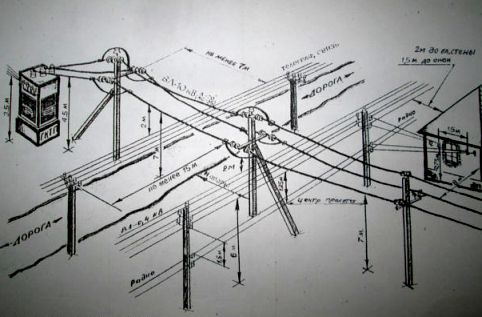
The main design parameters of the overhead line (VL)- this is the length of the span, the sag of the wires, the distance from the wires to the ground, to the covering of the roads intersected by the line and other engineering structures (gauge).
Intermediate span length called the distance along the line, between two adjacent intermediate supports. The span length of the 0.4 kV overhead line ranges from 30 to 50 m and depends on the types of supports, brand, wire section, as well as the climatic conditions of the area.
Wire sag call the vertical distance between an imaginary straight line connecting the attachment points of wires on two adjacent supports and the lowest point of their sag in the span. The sag depends on the same factors as the span length.
The size of the overhead line is the smallest vertical distance from the wires to the surface of the earth, rivers, lakes, communication lines, highways and railways, etc. The size of the overhead line also depends on the voltage and visiting the area by people.
To ensure normal operation and safe maintenance of overhead lines, the distances from them to various structures must comply with the standards established by the PUE. So, the vertical distance from the wires to the ground surface with the largest sag boom should be at least 6 m in a populated area, the distance from the wires to the ground can be reduced in hard-to-reach areas up to 3.5 m and in inaccessible areas up to 1 m. Distance 4 along horizontal from wires of overhead lines to balconies, terraces, windows of buildings should be at least 1.5 m, and to blank walls at least 1 m. Passage of overhead lines over buildings is not allowed.
The overhead line route can pass through forests and green spaces. The horizontal distance from the wires to the crowns of trees and bushes with the largest sag must be at least 1 m.
The angle of intersection of overhead lines with streets, squares, as well as with various structures is not standardized. Intersections of overhead lines up to 1 kV between each other are recommended to be carried out on cross supports, and not in spans.
Crossings of overhead lines with overhead communication and signaling lines should be carried out only in the span of the line, and the wires of the overhead line should be located higher.
The distance between the upper wire of the communication line and the lower overhead line must be at least 1.25 m. Special requirements are imposed on the wires of the overhead line in the crossing span: they must be multi-wire, with a cross section of at least 25 mm2 (steel and steel-aluminum) or 35 mm2 (aluminum) and fixed on supports with double fastening. , limiting the span of the intersection with communication lines of classes I and II, must be anchor; at the intersection with communication lines of other classes, intermediate supports are allowed (wooden ones must have reinforced concrete attachments).
When crossing underground cable communication and signaling lines, the overhead line supports should be located at the greatest possible distance from the cable (but not less than 1 m between the grounding of the support and the cable in cramped conditions).
Rapprochement of overhead lines with overhead communication lines allowed at a distance of at least 2 m, and in cramped conditions - at least 1.5 m. In all other cases, this distance is taken not less than the height of the largest support of the overhead line or communication line.
When crossing non-electrified main railways general use, transitional supports of overhead lines must be anchor; access railway tracks are allowed to cross overhead lines at intermediate (except wooden) at an angle of at least 40 degrees. and as close as possible to 90 degrees. electrified railways must be crossed by a cable insert in the overhead line.
Crossing overhead lines of highways Category I must be carried out on anchor supports, other roads may be crossed on intermediate supports. The cross section of overhead lines passing over highways must be at least 25 (steel-aluminum and steel) and 35 mm2 (aluminum). The smallest distance from to the roadbed should be at least 7 m. When crossing tram and trolleybus lines, the smallest distance from the overhead line wires to the ground surface should be at least 8 m.
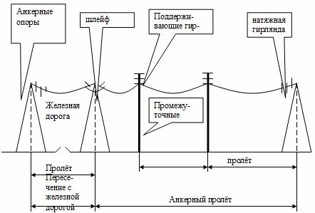
The figure shows a diagram of the anchor span of the overhead line and the span of the intersection with the railway.
The vertical distance from the line wires to the ground surface in an uninhabited area during normal operation should be at least 6 m for overhead lines up to 110 kV, 6.5; 7; 7.5; 8 m, respectively, for 150, 220, 330, 500 kV overhead lines.