How is a motor selected? The choice of the electric motor depending on the conditions of its operation
The choice of electric motors is made according to the following parameters and indicators: type of current and rated voltage, rated power and speed, type of natural mechanical characteristic, as well as starting, adjusting, braking qualities and design. An important task is the correct choice of motors for operation in certain environmental conditions.
When choosing an engine for power, it is important to provide for its full use in the process. An engine with an overestimated, compared to the required, power operates underloaded and has the worst efficiency and power factor. A low power motor will be overloaded with current, which will lead to large energy losses and, as a result, the temperature of its windings will exceed the allowable one. Therefore, the temperature of the motor windings is the main criterion by which the motor is selected in terms of power.
In some cases, the task of choosing a motor by power is further complicated by the fact that the load on its shaft during operation does not remain constant, but changes over time, as a result of which the temperature of the motor windings changes. If the change in the load on the motor shaft over time is known, then it is possible to judge the nature of the change in energy losses in the motor, which makes it possible to select the motor in such a way that the temperature of its windings does not exceed the permissible value. In this case, the condition for ensuring reliable operation of the engine during the entire period of its operation will be observed.
For short-term work motors designed for continuous operation may be used.
For intermittent operation, as a rule, specially designed engines are used. All their technical data are given in the catalogs for standard duty cycles. For example, if the engine passport for driving the compressor of an electric locomotive indicates that PV = 50% (21 kW), then it is possible to realize a power of 21 kW without fear of overheating, only during the working time, which is 50% of the cycle duration. The rest of the cycle time (50%) the engine should not run (pause). One and the same engine allows operation at different duty cycles. But the more PV, the less should be its load.
The continuous mode can proceed with a constant or variable load. The rated power indicated in the catalog is the maximum power that can be developed by the engine with a constant load on its shaft.
The choice of a motor operating for a long time with a variable load (the load diagram is shown in Fig. 1) is made according to the method of average losses or the methods of equivalent current, torque and power.
Method of average losses.
It is based on the assumption that the engine will operate according to a given load schedule without exceeding the allowable temperature, if the average losses of this load schedule Σрср do not exceed the total energy losses at the nominal operating mode of the engine Σрnom, i.e. the condition is met ![]() (1)
(1)
Knowing the nominal values of efficiency t] nom and useful power and using the formula, you can determine the total energy loss in the nominal mode:
(2)
Let any time interval tu according to the load diagram of loss change in Fig. 1 corresponds to the power Pi realized by the engine, at which the total losses in it are 2/7/. Then the average losses for the entire time of engine operation
(3)
The average loss method is quite accurate and can be used to select any type of motor. However, it requires specific loss calculations for each section, which is not always feasible.
Equivalent current method.
Based on the average loss method. In this case, it is considered that the average losses are created in the motor loaded with such a calculated constant (equivalent) current /ek, which releases the same amount of heat during operation as the actual currents. The load factor corresponding to the current /ek is called equivalent: ku e = /ek/Unom.
Then, according to expressions (13.7) and (15.8), we have: 
Rice. 1. Load diagram and change in losses in the motor during continuous operation in variable load 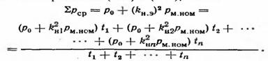
Substituting here the values of the load factors, excluding the terms with p0, reducing the rest by Rm.vonom and converting, we find the value of the equivalent current
(4)
where in is the duration of a full cycle of the engine. The engine is selected correctly if the condition is met
(5)
The equivalent current method based on the average loss method can also be used to select any motor.
Equivalent moment method.
Recall that the torque of the motors direct current parallel and independent excitations, as well as synchronous, according to the expression, M \u003d s "m / I
This circumstance allows us to introduce the concept of the equivalent moment MEC corresponding to the equivalent current /ek:
Therefore, similarly to (15.19), the expression for the equivalent moment has the form
(6)
Condition for the correct choice of engine ![]() (7)
(7)
Method of equivalent power. Allows you to evaluate the heating of the engine through the equivalent constant power Rack (power, which, according to the conditions of heating, is equivalent to the actual changing power). This method is applicable in those cases when, when the load changes, the angular velocity of the engine remains constant or changes slightly, i.e. Ω = const (hard natural mechanical characteristic).
Since Pnom = MnomΩnom and Rek = A * ekΩnom - from (6) we obtain the expression for the equivalent power
(8)
The engine is selected correctly if the condition is met ![]() (9)
(9)
Equivalent torque and power methods are applicable for preliminary motor selection and calculations that do not require great accuracy. These methods are completely unacceptable for series-excited DC motors, since their magnetic flux and rotational speed change dramatically with a change in load current.
The motor selected by any of the methods must also be checked for permissible overload so that the maximum values of current, torque or power (according to the load diagram) do not exceed the corresponding values \u200b\u200ballowed for this motor.
The correct choice of engine power for a particular mechanism, taking into account its technical regime, is of great importance for technical, economic and operational indicators. If the power of the electric motor is underestimated when choosing, then the electric motor will not provide the necessary reliability and durability. The dependence of the power factor on the load is shown in the graph. If an overpowered EM is selected, i.e. with a low load factor, it has low economic and energy performance.
Therefore, they try to select the ED in such a way that Рnom=Kzap*Ref.
In this case, the effective power is determined using the load characteristic, and the safety factor is introduced taking into account the inaccuracy of the load characteristic graph.
EM power selection sequence:
1. Pre-selection of power: consists in the analysis of the load diagram and the choice of Kzap.
2. Checking the correctness of the preliminary selection according to the thermal regime. Produced by accurate analysis.
3. It is checked for the possibility of launch.
4. Checking the correctness of the choice for short-term mechanical load.
Engine power selection for continuous duty:
A) under constant load.
In this case, a preliminary calculation of the power is not required, but the effective power of the mechanism is determined using exact or empirical expressions, which is then compared with the rated power of the engine. There are certain formulas for calculating the effective power of various types of mechanisms. If Ref< Рном, то двигатель выбран правильно. Причем в этом случае это соотношение является критерием правильности выбора и по нагреву, и по условиям правильности пуска, и по критериям качества.
For any modes with varying load, the choice of power is a much more difficult task and consists of several stages, the main of which is checking the correctness of the choice for heating. At the same time, for any mode, the most accurate method of such a check is the construction of a heating curve of a real engine, taking into account its mode, followed by comparison of tset< tдоп.
B) with a variable load.
 |
Let the load diagram look like:
Engine power selection sequence:
1. The engine is pre-selected, for which the arithmetic mean value of the power according to the load diagram is compared with the rated power according to the catalog.
2. They check the correctness of the choice of the engine for heating. This verification can be carried out using the universal loss method, since the calculation and construction of heating curves is a complex and not always solvable task.
According to a given load schedule, the average power losses for the engine operating cycle DPav are determined, which are then compared with the nominal power losses in the engine.
If the condition DРav £ DРnom is satisfied, then the engine meets the heating conditions.
DP1, DP2,…, DPn - power losses in each section of the load diagram;
hi - efficiency in the i-th section of the load diagram
3. Checking the correctness of the choice according to the launch conditions (if possible). For this, Mstart ³ M1, if not performed, then choose an engine with either improved starting properties or greater power.
4. The engine is checked for short-term mechanical overload. For this, the critical moment of the engine according to its passport is compared with the maximum moment according to its diagram.
If condition 4 is met, then the engine is selected correctly, if not, then the engine is selected either with a greater overload capacity or with a greater power.
However, despite the fact that the average loss method is sufficiently accurate and universal, i.e. can be applied to any type of engine, there are some difficulties. Therefore, in engineering calculations, less accurate and universal methods of equivalent quantities are most often used, which include:
A) equivalent current method
B) method of equivalent moments
C) the method of equivalent powers.
Equivalent current method:
It is based on the fact that the real current, corresponding to the load diagram and changing accordingly, is replaced by a certain equivalent current, which, during the operating cycle, releases the same amount of heat in the motor as the actually changing current.
In this case, the power loss in the engine:
Most often, the load diagram of the electric field is specified precisely in the coordinates M(t), therefore, from this point of view, the method of equivalent moments is more convenient. However, the exact proportional dependence M(I) is typical only for DPT with NI. For AM, the moment also depends on the power factor cosj. Therefore, in relation to blood pressure, this method does not provide sufficient accuracy. It is usually used for low power IM and in the linear part of the characteristic.
Equivalent power method:
It is based on the proportional dependence of power on the moment: Р=М×w, Р º M. The criterion for the correct choice is: Рnom ³ Req. Of all the listed methods, the equivalent power method is the least accurate and is used only for DCTs with NV.
Motor power selection for short-time operation:
Motors are serially produced, in the passport of which the nominal duration of switching on is set to 10, 30, 60, 90 minutes. In addition, the efficiency is set when operating in a short-term mode and Pcr; in long hpr and Rpr.
Рt=DРcr/DРpr=tset/t¢set=tset/tadm.
Selection sequence:
In the passport of serially produced motors for short-term duty S2, in addition to the on-time, the power during short-term operation, efficiency during short-term operation, power and efficiency in continuous operation are indicated.
1. Determine DРcr and DРpr:
DРcr=Рcr*(1-hcr)/hcr;
DРpr=Рpr*(1-hpr)/hpr;
2. Determine the coefficient of thermal overload: Рт=DPcr/DPpr.
3. Тн=tр/(ln(1-Рт)/Рт). Substituting tr from the passport and the thermal overload coefficient from the previous paragraph, we find the heating time constant Tn, with which you can easily build an engine heating curve and select the engine power from this curve.
Choice of engine power for intermittent operation modes:
For modes S4 and S5, engines commercially available for mode S3 with standard PV% = 15; 25; 40; 60% are usually used, or engines commercially available for mode S1. In this case, when choosing engine power, duty cycle = 100% is assumed. Most often, the method of equivalent moments is used as a mathematical apparatus for checking the correctness of the choice for heating. At the same time, in the equivalent torque formula, correction factors are introduced, which have the designation b(), and which take into account the deterioration in the heat transfer of the engine during acceleration, deceleration, pause compared to heat transfer when working with w=const.
c) The found value of Mekv is brought to the standard PV% and Mekvpriv is found:
 |
d) according to the catalog, an engine is selected, in which Mnom ³ Mekvpriv.
After that, the motor is checked for starting capability and short-term overloads in the same way as for S1 with a variable load.
The task of choosing an electric motor includes:
choice of type of current and rated voltage;
choice of nominal speed;
choice of design;
determination of the rated power and selection of the motor corresponding to it from the catalogue.
In production conditions, it is not always necessary to solve the whole complex of these issues. Some of them can be given: type of current, voltage, speed. The main importance in this case is the correct determination of the power and design type of the engine.
Before solving the problem of choosing an electric motor, it is necessary to clearly imagine the operation of the mechanism for which it is selected: whether the motor with the mechanism will work for a long time or for a short time, at a constant or adjustable speed, whether (and how) the moment of resistance and power will change during operation. The answers to these questions can be given by the construction of load diagrams. The questions are then answered in the order listed.
Choice of motor current and voltage . This choice is based on economic considerations. Electric motors have a high cost, as they are complex products that use valuable electrical materials designed for a long service life (20 years). Therefore, the choice begins with a “fitting” of suitability for driving the simplest and cheapest motors - three-phase asynchronous with a short-circuit rotor, and up to the most complex and expensive - DC motors.
The choice of the type of current of the electric motor determines the choice of its rated voltage, which is usually taken equal to the voltage of the power supply of the workshop, factory, construction site (most often it is three-phase network with main voltage 380.220 V). Increasing or decreasing the voltage for motors using transformers, the use of rectifiers for DC motors leads to an increase in the cost of electrical equipment.
Motor rated speed selection. The high speed of the electric motor allows to reduce its overall dimensions, weight and cost. Working mechanisms, on the contrary, often require reduced speeds. To match the speeds of the engine and the mechanism, a gearbox is installed, which increases the cost of the electric drive. The question of the rational ratio of the motor-reducer is decided by the designer when designing the mechanism.
The choice of the design of the engine. The design of modern series of electric motors takes into account three factors: protection against environmental influences, provision of cooling and installation method.
In table. 1 shows an approximate sequence for choosing the type of electric motor, depending on its purpose.
Table 1.1
Approximate motor type selection sequence
engine's type | Purpose |
Asynchronous with short-circuit rotor of normal Versions | For an unregulated drive that does not require large starting torques, with |
Asynchronous with deep-slot short-circuit rotor or double squirrel cage | The same if high starting torques are required |
Asynchronous with slip rings | Frequent starts at high starting torques and low currents, speed regulation (rheostat regulation uneconomical) |
Synchronous | For an unregulated drive in continuous operation, cos regulation (at Р |
Direct current | Speed regulation in a wide range, ensuring good starting qualities, overload capacity |
 100 kW, SM is more economical than IM)
According to the method of protection from environmental influences, electric motors are manufactured in protected, closed and explosion-proof versions.
The motors, protected from small objects and drops, are designed for operation in dry, dust-free rooms.
Closed engines are installed in rooms with high humidity, an atmosphere polluted with dust with metal inclusions, oil or kerosene vapors.
Explosion-proof motors have a housing that can withstand a gas explosion inside the machine and thus exclude the release of flame into the environment. They are intended for work in explosive rooms (mines). On the cover of the terminal box of these motors there is a relief sign PB - mine explosion-proof or VZG - explosion-proof in a gaseous environment. Without these signs, the use of engines in explosive environments is prohibited. It is also impossible to install a protected one instead of a closed engine.
According to the method of cooling, engines are distinguished with natural cooling, internal or external self-ventilation and external blowing (forced).
According to the mounting method, there are motors with a horizontal shaft arrangement and a bed on the legs, with a vertical shaft arrangement and a flange on the bottom shield, etc. The selected motor must have the same installation, fastening and connection to the mechanism as the one being replaced.
The choice of engine power. The final step is to determine the rated power of the motor and select the appropriate motor from the catalog. However, the rated power is easy to determine only during long-term operation with a constant load, which is taken as the rated one. In the vast majority of cases, the torque, power and current of the motor change over time. Load diagrams of engines of many mechanisms include periods of work and pauses. With such a variable load, the motor must satisfy the conditions of allowable heating, have a maximum torque sufficient to overcome possible short-term overloads and, when starting with a heavy load, have an excess starting torque to ensure drive acceleration.
1.3. Heating and cooling of electric motors
The operation of the electric motor is accompanied by the loss of part of the energy, which is converted into heat. Power loss
Р = Р(1/ - 1) (1.10)
the more, the more power P the engine develops on the shaft and the lower its efficiency. Therefore, with increasing load, the temperature of the engine will increase and may reach dangerous values.
According to heat resistance, insulating materials are divided into several classes. So, class A insulation (impregnated fibrous materials) allow heating temperatures up to 105 0 C; class B (materials based on mica, asbestos and fiberglass with impregnation) - up to 130 0 C, and the same materials with organosilicon binders - up to 180 0 C (class H).
The specified operating temperatures are based on the service life of electric motors of 15-20 years at rated load. With a load of 1.5 rated motor fails after 3 hours.
The temperature of the engine depends not only on its load, but also on the temperature of the coolant. In calculations, it is taken equal to +40 0 C. The difference between the temperatures of the engine and the cooling medium is called the temperature rise or overheating temperature and is denoted . For example, for widespread class A insulation, the allowable overheating temperature is 65 0 C.
When calculating the processes of heating and cooling of electric motors, an electric machine is simply considered as a homogeneous body that heats up uniformly and radiates heat to the environment with its entire surface. Before operation, the engine has an ambient temperature, so all the heat released in it goes to increase the engine temperature, respectively, heat capacity C, Wts / deg. When its temperature becomes higher than the ambient temperature, the process of heat transfer to the environment begins. At a constant load, after a while the temperature of the engine reaches a steady-state value, at which all the heat released in the engine is given off to the environment. There is thermal equilibrium.
The heat balance equation for an electric motor at a constant load has the form
Pdt = Cd + Adt, (1.11)
where d - overheating, deg., corresponding to the time element dt, for which energy Pdt is released; A - heat transfer during heating, W / deg.
From the moment of thermal equilibrium, the engine temperature rise stops (d = 0). The steady state overheating temperature is determined by the expression
mouth \u003d P / A. (1.12)
Each engine load has its own set temperature. Obviously, the motor can only be loaded with such power at which the steady-state overheating of its insulation does not exceed the maximum allowable value. This power is called nominal.
It can be seen from expression (1.12) that the steady-state overheating increases with a decrease in heat transfer A. The better the engine cools during operation, the lower the steady-state overheating. Therefore, the engines are equipped with fans and ribbed housings are used to increase the cooling surface.
We divide equation (1.11) by Adt and, taking into account (1.12), we rewrite it in the form
 (1.13)
where Тu = С/А is the heating time constant.
The solution of this linear differential equation gives the law of engine temperature change over time:
where start is the initial temperature rise with which the engine starts to work.
If the engine starts in a "cold" state, then start = 0 and
 (1.15)
On fig. 1.5 shows the exponential heating curves of the electric motor at a constant load. Curves 1 and 2 correspond to the operation of the engine from a “cold” state ( initial = 0) at low (1) and high (2) loads, curve 3 corresponds to operation when the engine already had an initial temperature rise initial = 03.
Curve 3 can be considered as an excess of the engine temperature if the ambient temperature has increased by 03 compared to curve 2. The steady temperature is reached almost in time (3  5) T i.
The heating and cooling curves are exponential. The steady temperature is reached almost within the time (35) T and (error 5 and 0.5%, respectively).
After disconnecting the engine from the mains, the release of heat in it

Rice. 1.5. Motor heating and cooling curves
stops: P = 0, set = 0, and the expression (1.14) for the cooling process will take the form
start e - t / T cool, (1.16)
where T cool = C/A cool; A cool - heat transfer during cooling.
The engine cooling curves are shown in fig. 1.5. Cooling time of the electric motor to the steady temperature or to the ambient temperature t cool = (35) Т cool. The intensity of engine cooling depends on the ventilation method and its speed. In a stationary engine, with self-ventilation, the cooling conditions are much worse than in a rotating one. Therefore, the cooling constant Tcool here is 2-3 times greater than Tu. During operation, regular purges and cleaning of the engine surface from dust increase heat transfer and ensure its fullest use.
1.4. Rated operating modes of electric motors
When considering the laws of heating and cooling of electric motors, it was assumed that the engine load is unchanged for a long time, therefore, the established limiting overheating set is also unchanged. In reality, the motor load can vary in different ways in value. In addition, the engine may turn off for a while.
To take into account the various operating conditions of the electric motor and correctly determine its power, load diagrams M (t), P (t) (see Fig. 1.4) or I (t) are calculated and built. By the type of load diagram determine the mode of operation of the engine. Modes are standardized. There are three main modes: long-term (S1), short-term (S2) and intermittent (S3). For each of them, the conditions for heating and cooling are different.
Long mode. Long-term is the mode in which the temperature of the electric motor reaches a steady value.
Distinguish between a long mode with constant and variable loads. Fans, pumps, compressors, some conveyors, textile machines work for a long time with a constant load. The load diagram for this mode is shown in fig. 1.6, a.
Reciprocating compressors, rolling mills, turning, drilling, milling machines, etc. work for a long time with a variable load (Fig. 1.6, b).

Rice. 1.6. P(t) and (t) diagrams of the engine in long-term mode with
constant (a) and variable (b) loads
On the shield of an electric motor designed for continuous operation, the nominal mode is indicated by the abbreviated word "Dur." Or the symbol S1.
Momentary duty . In this mode, the electric motor runs for a limited time, during which the temperature does not reach a steady value. Pauses in work are so great that the engine has time to cool completely. The load diagram and motor overheating in short-term mode are shown in fig. 1.7.
In the short-term load mode, auxiliary drives of machine tools, drawbridges, locks, valves for pipelines and gas pipelines and other mechanisms operate. The nameplate of the intermittent duty motor indicates the operating time at rated power: 30, 60 and 90 minutes and the symbol S2. For universal use, short-time duty motors are not produced in large series.
Intermittent mode. In this mode, short periods of operation regularly alternate with short periods of pauses, and during the load period, the engine temperature does not reach a steady value, and during the pause (shutdown) period, it does not have time to drop to the level of the coolant temperature. Graphs of such a regime are shown in Fig. 1.8. The overheating of the electric motor changes along a sawtooth broken line, consisting of segments of the heating and cooling curves. With repeated repetition of cycles, overheating fluctuates around a certain average value cf.

Rice. 1.7. P(t) and (t) diagrams 1.8. Diagrams Р(t) (t)
engine in short engine in re-
temporary mode short-term mode
work work
A typical example of intermittent operation is the electric drives of cranes, as well as the electric drives of most metal-cutting machines.
The electrical industry produces special crane motors designed to work in lifting and transport devices. On the shield of such an engine, in the column "operation mode", the symbol S3 and the relative duty cycle PV% (also denoted by ) are indicated:

Rice. 1.9. Real (a) and idealized (b) P(t) diagrams
engine in intermittent mode
 (1.17)
where t p is the operating time; t p - pause duration; t c - cycle duration.
The duration of the intermittent mode cycle for crane electric motors according to GOST should not exceed 10 minutes.
The value of PV is standardized and is 15, 25, 40 and 60%. For example, if on the shield of the crane motor P nom = 11 kW at 40% duty cycle is indicated, this means that this motor can operate with a rated load of 11 kW for 4 minutes, and for the next 6 minutes it must be disconnected from the network.
The actual diagram may look like Fig. 1.9, a, under load, when its duration and pause are not the same. In this case, an equivalent (idealized) diagram is built (Fig. 1.9, b), where t c \u003d t p +t p, and PV \u003d t p /t c.
1.5. Power calculation and motor selection
for continuous operation
Determining the rated power of the engine for continuous operation with a constant load (see Fig. 1.6, a) is reduced to calculating the power P from the actuator, reduced to the engine shaft (taking into account the efficiency of gears, gearboxes, etc.). According to the received power P in the catalogs, a motor with a rated power P nom R s is selected (the type of current, voltage, frequency and design of the motor are pre-selected). The rated power indicated in the catalog is the maximum power that the engine is designed for continuous operation without the risk of overheating. Since the load is constant, no special thermal check is required. Under difficult starting conditions, it is checked whether the starting torque developed by the motor is sufficient.
Determination of the rated power of the motor under long-term variable load is carried out by the method of average losses or by the method of equivalent values (current, torque, power). These methods consist of a thermal check of a pre-selected motor. Preliminarily (tentatively) the engine is selected according to the average load power (see Fig. 1.6, b):
 (1.18)
where k = 1.11.3 is the safety factor.
According to the preliminary power R pr in the catalog, an engine with a rated power R nom R pr is selected, and then one of the methods is used to check it for heating.
The choice of the motor according to the average power is incorrect because it does not take into account the quadratic dependence of the variable losses on the current. With large load fluctuations, the average power is underestimated.
If, for a given variable load schedule (see Fig. 1.6, b), the electric motor is selected according to the highest or lowest power, then in the first case it will be overestimated, and in the second - underestimated. The use of an overpowered engine increases capital costs, leads to a decrease in efficiency, cos. The use of a motor with insufficient power reduces the performance and reliability of the electric drive, shortens its service life.
These circumstances determine the need for other methods for choosing the rated power of the engine with a variable load - the method of average losses and the method of equivalent values.
Method of average losses. With a constant load on the shaft (P nom), the power loss remains unchanged (P nom). When the load changes, the power loss also changes. It is considered that the engine heats up equally if the average power loss (P cf) during the cycle at a variable load is equal to the power loss at a constant rated load:
P cf = Р nom (1.19)
(this is true if the duration of the cycle is much less than the duration of the heating of the engine).
Thus, first, for a pre-selected motor, according to formula (1.10), the nominal losses Р nom are determined, and then the losses P 1, P 2, ... in each section of the load graph (see Fig. 1.6, b). Then find the average losses by the formula
 (1.20)
and check the fulfillment of condition (1.19). If the value of P nom exceeds Р av by more than 10%, then select another motor and repeat the calculation. This method is quite accurate, applicable to the choice of engines of any type, but it is laborious.
Method of equivalent values (current, torque, power). Variable losses in the motor are proportional to the square of the load current. Load currents that change in value are replaced by an equivalent unchanging current I eq, which releases the same heat in the motor as changing currents. The equivalent current formula can be obtained based on expression (1.20):

 (1.21)
The found current I eq is compared with the current I nom of the pre-selected motor. The correct motor is selected if
I nom I eq. (1.22)
More often they deal with a graph of moments or powers. If the motor torque is proportional to the current, then formula (1.21) turns into the equivalent torque formula:
 (1.23)
The motor selection is considered correct if the rated torque of the pre-selected motor
M nom M eq.
If the engine speed does not change significantly when the load changes, then the equivalent power can be determined
R eq = M eq
 (1.24)
The condition for the correct choice is the inequality
R nom R ek.
Equivalent torque and power methods are not applicable to series motors where the torque is not proportional to the current.
The selected motor is subject to mandatory checks for overload capacity and starting torque (if starting under load).
Instantaneous overload capacity m = M max / M rated motors of different types has the following values.
Overload capacity m motors
General purpose DC. . . . . . . . . . . . 2
Special (traction) direct current. . . . . . . . 3-4
Asynchronous with slip rings. . . . . . . . . . . 2-2.5
Asynchronous with short-circuit rotor of normal execution 1.8-3
Asynchronous deep groove with double cage. . . . . 1.8-2.7
Synchronous. . . . . . . . . . . . . . . . . . . . . . . . . . . . . . . . . . 2-2.5
Synchronous special. . . . . . . . . . . . . . . . . . . . . . 3-4
Collector alternating current. . . . . . . . . . . . . . . . . 2-3
If the maximum load torque is greater than the motor can develop, then a larger motor is selected.
Flywheel drive. For mechanisms with shock loading (hammers, presses, stamping machines, etc.), the electric motor would have to be selected not for heating, but for mechanical overload, which would lead to an overestimation of power. But the engine power can be reduced and brought closer to the required heating, if the load curve is "levelled" using the flywheel.
During periods of a sharp increase in load (P 1 in Fig. 1.10), part of it is covered by the engine, and part is covered by the flywheel, which gives off its kinetic energy. During load shedding (up to P 2), the speed of the drive increases and the energy reserve in the flywheel increases again. Thus, the electric motor will develop power that is less than P 1 and more than P 2; the equivalent power approaches the average power P. Therefore, the use of a flywheel reduces the rated power of the engine. But the engine must have a sufficiently soft mechanical characteristic.

Rice. 1.10. Graphs Р(t) and (t) flywheel drive
When replacing an electric motor with a flywheel drive, the motor should be selected in the same way as the one being replaced.
Food industry (4)
Training and metodology complexFOR EDUCATION RF KEMEROVSK TECHNOLOGICAL INSTITUTE FOODINDUSTRY Department of Fermentation Technologies and... of the RUSSIAN FEDERATION Kemerovo Technological Institute foodindustry Department "Technology of fermentation production and...
Food industry (3)
Laboratory workFOR EDUCATION Kemerovo Technological Institute foodindustry Department: "Technology and organization of public ... copying equipment of the Kemerovo Technical Institute foodindustry 650010, Kemerovo, st. Krasnoarmeyskaya, ...
Food industry (6)
TutorialRoshnik V.A., Rekhovskaya T.A. - Kemerovo Technological Institute foodindustry. - Kemerovo, 2000. - 132 p. ISBN ... technical universities. © Kemerovo Institute of Technology food
The operation of the electric drive and its energy performance during operation depend on the correct choice of the electric motor in terms of power. In cases where the load of the electric motor is significantly less than the nominal, it is underused in terms of power, which leads to excessive capital investments, a noticeable decrease in power factor and efficiency. If the load on the motor shaft exceeds the nominal value, the currents in its windings increase, as a result of which the temperature of the motor may exceed the permissible value. This, first of all, leads to a decrease in the electrical strength of electrical insulating materials, which is associated with the danger of breakdown of the insulation of the windings and the failure of the electric motor. In this case, one of the criteria for choosing an electric motor in terms of power is the temperature of its windings.
The task of choosing an electric motor in terms of power is further complicated by the fact that the load on its shaft during operation changes over time, and the temperature of the windings changes accordingly. If, under these conditions, the electric motor is selected in such a way that its rated power is equal to the maximum load power, then during periods of its decrease it will be underused in terms of power, which means that all the negative phenomena mentioned above will begin to appear.
The choice of an electric motor with a rated power equal to the minimum load power is generally unacceptable in terms of overload capacity and temperature conditions.
Therefore, a reasonable decision on the choice of an electric motor can only be made on the basis of diagrams of the dependence of changes in loads over time, which makes it possible to estimate its temperature with a known nature of the heating process. This will ensure reliable operation of the electric drive during the entire period of its operation and is the first prerequisite for the correct choice of the electric motor, taking into account the mode of operation of the mechanism.
The second prerequisite for the correct choice of an electric motor is that its overload capacity must be sufficient for its stable operation during periods of maximum load.
The third condition for the correct choice of the electric motor is to ensure the normal process of its start-up.
Rated operating modes of electric motors
The mode of operation is the established order of alternation, duration and magnitude of the load, idling, braking, starting and reversing the machine during operation.
The nominal mode of operation of the electric motor is the mode for operation in which the electric machine is designed by the manufacturer. This is one of the parameters of its technical characteristics, given in the passport or catalog. It is for this mode that the catalogs and passport of the electric motor indicate the rated useful mechanical power on the shaft, rated voltage, rated current, rated speed, rated efficiency, rated power factor, rated operating mode.
Rated data characterize the operation of an electric machine installed at an altitude of up to 1000 m above sea level, at an ambient temperature of 40С and cooling water 30С 1 .
In accordance with GOST 183-74 (ST SEV 1346-78), eight nominal modes of operation of electrical machines are established, which, in accordance with the international classification, have conventions S1 - S8.
Continuous load modeS1 (continuous mode) called the mode in which the operating time of an electric machine at a practically constant load and temperature of the cooling medium is sufficient to heat all its parts to a practically steady temperature, fig. 3.1a. The mode is characterized by constant heat losses during the entire operation time.
Mode of short-term loadS2 (short-term mode) call the mode in which periods of work with a constant load alternate with periods of shutdown of the electric machine (pauses), fig. 3.1b, moreover, during operation, the temperature of its parts does not have time to reach a steady value, and during pauses (shutdowns) it cools down to a steady temperature, which differs from the ambient temperature by no more than 1С. The duration of periods of operation in this mode established by GOST is 10, 30, 60 and 90 minutes. It must be indicated in the operating mode symbol, for example S2-60 min.
Intermittent load mode (intermittent) has three varieties S3, S4, S5. It differs from the short-term regulated by the duration of switching on under a constant load and the duration of shutdown periods (pauses). The operating time of an electrical machine is always less than the time required to heat its parts to a steady temperature, and the pause time is shorter than that required for the machine to cool down to a practically cold state. Cycle duration 10 min. (600 s.), unless otherwise indicated.
Intermittent load modeS3 – a sequence of identical operating cycles, each of which consists of periods of operation at a constant load and a disabled stationary state, fig. 3.1c. Since the duration of the starting period is much less than the period of operation under load, it is assumed that there is no effect on the heating of the electric machine of the starting current and an increase in the power of heat losses during the start-up. For mode S3 characterizing is only one parameter - the duration of the inclusion:
where  – period of operation under nominal conditions, s.;
 – period of disconnected, immobile state, s.;
 – duration of the cycle, s.
For all varieties S3, S4, S5 intermittent mode, the nominal duty cycle is assumed to be 15, 25, 40, 60%.
In mode symbol S3 the duty cycle is indicated in %, for example S3-40%.
Intermittent load mode, including start-up,S4 - a sequence of identical work cycles, each of which consists of start-up periods, work at a constant load and a disabled stationary state (pauses) Fig. 3.1d. The start-up time is commensurate with the time of operation under load, and therefore the starting current and the increase in the power of heat losses during the starting period have a direct effect on the heating of the electric machine (electric motor).
For mode S4 characterizing parameters are:
duty cycle

a– S1,b– S2 , b – S3,G– S4,d– S5,e– S6,and– S7,h– S8
t c - cycle time.
T, heat loss power R t

a– S1,b– S2 , b – S3,G– S4,d– S5,e– S6,and– S7,h– S8
t c - cycle time.
T, heat loss power DR t, motor temperature Q

a– S1,b– S2 , b – S3,G– S4,d– S5,e– S6,and– S7,h– S8
t p - start time; t p - operating time under nominal conditions;
t t - braking time; t x - idle time; t 0 - pause time;
t c - cycle time.
Figure 3.1 - Diagram of useful mechanical torque on the motor shaft T, heat loss power DR t, motor temperature Q at various nominal operating modes
inertia coefficient:
|
|

where t n– start time, s.;
 – moment of inertia of the armature (rotor) of the engine, kgm 2 ;
 – the moment of inertia of the drive mechanism reduced to the motor shaft, kgm 2 ;
 - the number of inclusions in one cycle.
Rated values:
 –30,
60, 120, 240;
–30,
60, 120, 240;
 –1.2,
1.6, 2, 2.5, 4, 6.3, 10.
–1.2,
1.6, 2, 2.5, 4, 6.3, 10.
![]() ,,, for example S4-25%, 120 on/hour,FI
- 2.0
. This means that the electric motor with an inertia coefficient =2.0 is designed for operation at 120 starts per hour, the duration of each cycle is 3600/120 = 30 s, of which the sum of the starting time
,,, for example S4-25%, 120 on/hour,FI
- 2.0
. This means that the electric motor with an inertia coefficient =2.0 is designed for operation at 120 starts per hour, the duration of each cycle is 3600/120 = 30 s, of which the sum of the starting time  and working time
  is 25% i.e. 7.5 s, and the pause time is 22.5 s.
Intermittent load mode, including starting and electrical braking,S5 – a sequence of identical operating cycles, each of which consists of periods of start-up, operation at a constant load, rapid electrical braking and a disconnected, stationary state, fig. 3.1d. The duration of these periods is insufficient to achieve thermal equilibrium during one cycle.
For mode S5 switching duration:
where  – electric braking time, s.
The rest of the parameters are the same as S4. Sometimes for the regime S5 they also use such a characteristic as the constant of kinetic energy - the ratio of the kinetic energy stored by the rotor (armature) of the electric machine at the rated speed (angular velocity) to the rated power of the electric machine.
The mode symbol is similar S4, for example S5 - 40%, 60 on/hour,FI - 1.2 .
ModesS6 , S7 , S8 are varieties of continuous mode and are called intermittent modes.
Continuous operation mode with variable load (intermittent mode)S6 - a sequence of identical work cycles, each of which consists of periods of work at constant load and at idle, Fig. 3.1e. The effect of starting currents and heat loss power on the heating of parts of the electric motor during the starting period is not taken into account.
Thermal equilibrium does not occur during one cycle. The duration of one cycle, if there are no other indications, is taken as 10 minutes (600 s). For mode S6 the characterizing parameter is the duration of the load (work):
|
|

where t x- time (duration) of idling, s.
Rated values  –
15, 25, 40, 60%.
–
15, 25, 40, 60%.
The mode symbol indicates in %, for example S6 - 15%.
Continuous duty including starting and electrical braking (intermittent duty with frequent reversals during electrical braking)S7 - a sequence of identical cycles, each of which consists of periods of start-up, operation at a constant load and electric braking, fig. 3.1 g. Due to the short duration of a constant load, losses during starting periods, during reverses, and electrical braking have a significant effect on the heating of engine parts. The duration of the working period is insufficient to achieve thermal equilibrium during one cycle.
For this mode, the characterizing parameters are: the number of starts per hour, the coefficient of inertia, for example S7 - 120 on/hour,
-2.5
.
Mode of operation with periodic changes in speed and load (intermittent operation with two or more speeds)S8 - a sequence of identical work cycles, each of which consists of periods of acceleration, operation at a constant load corresponding to a given speed, then one or more periods of work at other constant load values corresponding to other speeds, fig. 3.1z. The change in the power of the thermal losses of the electric motor during the transition to a different speed with a different load and during electric braking has a significant effect on the heating of parts of the electric motor.
For mode S8 characterizing parameters are: the number of inclusions per hour; inertia coefficient; load corresponding to each of the rotation frequencies; rotational speed at the corresponding load, duration of the load at each of the rotational speeds, fig. 3.1h:
|
| |
|
|


The mode symbol includes the above characteristics, for example S8 - 60 on/hour;  - 2.0; 22 kw; 740 rpm; 40%; 55kw; 1470 rpm; 60%.
In addition to the main nominal operating modes of electrical machines ( S1 – S8) in the practice of operating electric motors, one can distinguish: short-term load mode with a cycle time significantly less than 10 minutes; alternating reverse mode; stochastic load mode.
Mode of short-term load with a small duration of the duty cycle is a special case of modes S2, S3 and differs from them in that the operating time in this mode is commensurate with the starting time of the electric motor. In this regard, the losses in the electric motor must be considered as a function of time, and not as constants.
Alternate reverse mode refers to the mode S7, but differs from it in a symmetrical power graph for different directions of rotation. In addition, the duty cycle is comparable in time with the reversal time, and therefore, when calculating losses, it is necessary to take into account the aperiodic components of the current and magnetic flux.
Stochastic (random) load mode is characterized by probabilistic characteristics of the load on the shaft, and the random load graph cannot be expressed as a deterministic function of time.
Once again, we draw attention to the fact that the catalogs, passports for electrical machines indicate the nominal modes, and the technical data is for these nominal modes.
Since the operating mode of real machines and mechanisms, as a rule, does not coincide with one of the considered nominal ones, the task of choosing an electric motor in terms of power to drive a real machine, mechanism is to correctly compare its operating mode with the passport nominal mode of the electric motor, ensuring maximum use the selected electric motor according to the heating conditions.